Wavelet Applications in Communications
OFDM Review
OFDM or Orthogonal Frequency Division Multiplexing is a data transmission scheme that consists of transmitting a high rate data stream by using lower rate data streams modulated over orthogonal subcarriers. An OFDM transmission system consists of a constellation encoder followed by a serial-to-parallel converter and a FFT encoder which modulates the signal symbols over an orthogonal bank of subcarriers. The stream is then converted from parallel to serial and a redundant guard band is added to prevent Inter Symbol Interference caused by multipath propagation delays in wireless and other channels.Block diagrams of OFDM Transmitters and Receivers are shown in figures below.

OFDM Transmitter

OFDM Receiver
OFDM Stages
On the transmitter side, an OFDM system consists of
- 1. FEC Encoder : Wireless channels suffer from frequency selective fading which may result in wiping out of certain subcarriers.However, using a combination of error correction coding and interleaving, we can counteract some of the effects of this fading phenomena.IEEE 802.11a standard utilizes convolution coding in conjunction with Viterbi decoders at the receiver. Convolutional Encoders with encoders with bit rates of \(1/2\),\(2/3\) and \(3/4\) are typically used.
- 2. Constellation Encoders: In OFDM systems PSK (Phase Shift Keying) and QAM ( Quadrature Amplitude Modulation) are used to convert FEC-encoded bits to symbols.
- 3. Serial to parallel Converters: are used to convert serial stream into \(N\) parallel streams.
- 4. IFFT : IFFT stage is used to modulate these parallel streams into \(N\) orthogonal channels.
- 5. Serial to Parallel Converters : convert these parallel streams to serial stream.
- 6. Cyclic Extension: One of the biggest issues with wireless channel happens to be multipath delay. Any transmitted signal is prone to get reflected by obstacles in the path( buildings, trees etc.) and instead of receiver getting one copy of the signal, it may receive multiple delayed copies. OFDM uses lower rate subcarriers which helps with delay spread but in order to almost completely remove multipath delay cyclical extension is used in which last \(L\) subcarriers out of \(N\) [\(L \lt N\)] are folded back in front of each OFDM symbol in order to form one large \(L+N\) orthogonal symbol. As long as channel multipath delay is smaller than \(L\) all delayed copies of the given symbol continue to be orthogonal to the original symbol and they don't overlap with the next symbol and are , therefore cancelled out.
OFDM receiver stages are essentially the reverse of the transmission stages as can be seen from the block diagram. Mathematically,an OFDM signal \(x[k]\) can be seen as a series of ,say, \(s\) OFDM symbols each consisting of \(M\) orthogonally modulated waveforms.
\[ x[k]=\sum_{s}\sum_{m=0}^{M-1} a_{s,m} \phi_{m}[k-sM] \]where \(\phi_{m}[k]\) are \(M\) orthogonal waveforms such that
\[ \lt\phi_{m}[k],\phi_{n}[k] \gt = \delta[m-n] \]In the case of regular OFDM case, we use FFTs to implement orthogonal channels, such that
\[ \phi_{m}[k]=e^{\frac{j2\pi mkT}{M}} \]Advantages of OFDM
- 1. Orthogonality between subcarriers allows channel overlap and , thus, more efficient use of Bandwidth.
- 2. Orthogonality also helps in eliminating ICI ( Inter Channel Interference) as subcarriers are orthogonal to each other.
- 3. ISI ( Inter Symbol Interference) can be dealt with by using a guard band or cyclic prefix. Essentially, we don't use all subcarriers for data transmission. Instead some of the subcarriers use redundant information as data of the last \(L\) subcarriers is folded back and added as a prefix to the symbol. This cyclic prefix is discarded at the receiver and helps guard against things such as multipath effects where delayed copies of same symbol is received because of inefficiencies in wireless channel.
- 4. Use of lower-rate multiple subcarriers helps in dealing with noise by using proper channel coding. A loss of handful of subcarriers due to noise can be compensated by using error correction codes while noise in high rate single carrier systems may result in loss of entire stream.
Wavelet Packet Modulation
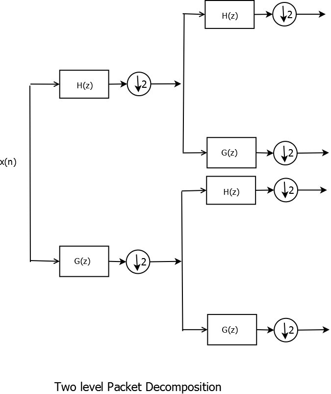
Since OFDM channels consist of \(M\) orthogonal subcarriers, we need \(M\)-band wavelet implementation if we want to substitute wavelet transform in place of DFTs. We achieve this using wavelet packet decomposition and reconstruction. Instead of dyadic iterations across only low pass filters, we dyadically decompose both high and low pass filters at every stage as show in the figure for two level wavelet packet tree decomposition.

Wavelet Two-level Packet Decomposition
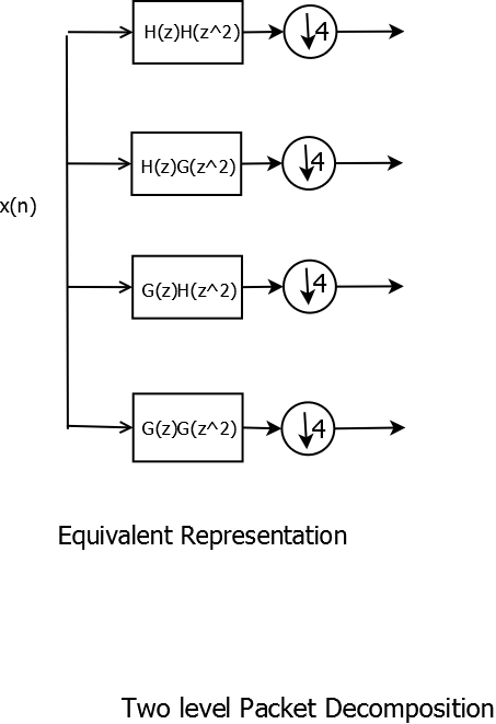
This wavelet tree is equivalent to one stage \(4\) band wavelet filter bank as shown in the figure.

WaveletTwo-level Packet Decomposition Equivalent Representation
Decomposition is done similarly for any \(M=2^{n}\). The filters of \(M\)-band wavelet transform are obtained using noble identities and iterated filter bank properties. They are respectively \(H(z)H(z^{2})\),\(H(z)G(z^{2})\),\(G(z)H(z^{2})\) and \(G(z)G(z^{2})\). Wavelets corresponding to these filters are computed using scaling and wavelet dilation equations. The dilation equations are different in the \(M\)-band case:
\[ \phi(t):= \sum_{k} hh(k)\phi(Mt-k) \]and
\[ \psi(t):= \sum_{k} gg(k)\phi(Mt-k) \]where \(hh\) and \(gg\) filters are iterated bandpass filters obtained using noble identities.
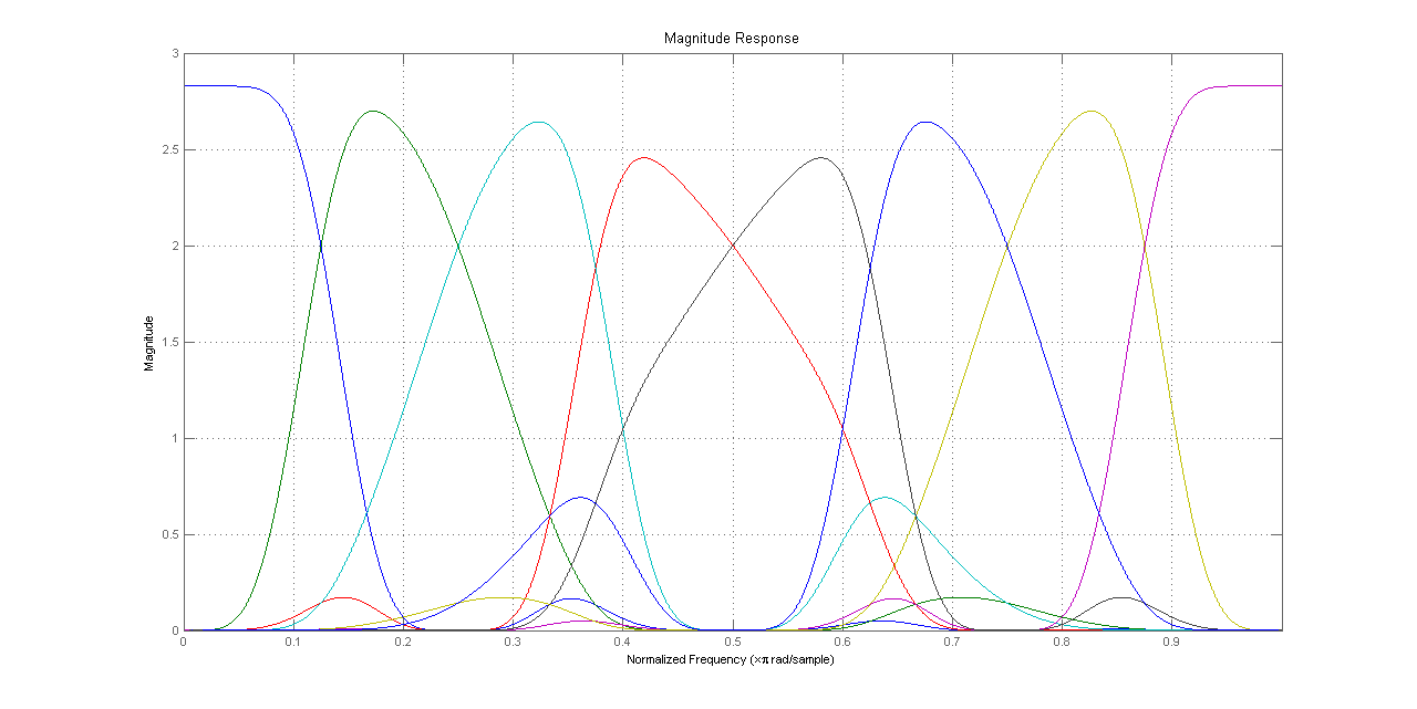
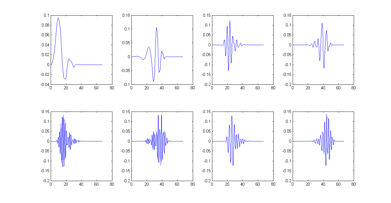
An \(M\)-band wavelet system has one scaling function corresponding to the low pass filter and \(M-1\) wavelet functions corresponding to each bandpass filter. For a three level wavelet packet decomposition using Daubechies orthonormal wavelets, the filters and \(M = 8\) wavelets[unnormalized] are plotted in Matlab.

8 Filters for 3-level Packet Decomposition Tree

Wavelets for 3-level Packet decomposition Tree
Wavelet Packet Based OFDM systems
Wavelet based OFDM systems are similar to regular OFDM with orthogonal subcarriers generated by iterated wavelet filter banks instead of DFTs but there are several crucial differences. Wavelet-OFDMs have better ISI and ICI performance. In addition, wavelet symbols generated are longer than DFT symbols. The length of iterated wavelet filters for \(M\) level wavelet packet decomposition is equal to \((M-1)(L-1)+1\) where \(L\) is the length of original filters. For higher level decompositions, iterated wavelet filters are significantly larger which results in longer subcarrier symbols. Guard Band or cyclical prefix is usually not needed in Wavelet OFDM case. A block diagram of Wavelet OFDM can, therefore, be given by

Wavelet-OFDM Transmitter

Wavelet-OFDM Receiver
Some properties of W-OFDM are following
- 1. Wavelet-OFDM has much better power spectrum characteristics than conventional OFDM which results in significantly improved band-rejection properties.For more on this , visit HD-PLC alliance webpage at HD-PLC Alliance .
- 2. Variable symbol lengths and variable subcarrier bandwidths can be easily obtained if we choose not to fully decompose each branch. This can be especially useful in wireless channels and other channels that suffer from frequency selective fading as it makes sense to not transfer same amount of data on each subcarrier.
- 3. Guard bands (cyclical prefix) is usually not needed (the WOFDM symbols are longer and they overlap which makes an effective cyclical prefix impossible to implement anyway) which results in more efficient data transmission. Additionally, pilot symbols( used for estimation and synchronization purposes in conventional OFDM) are not needed which adds to bandwidth efficiency.
- 4. WOFDM is entirely dependent on scaling filter (all other filters can be obtained from it) so it is much more flexible and we can design the system according to our needs by choosing the correct type of orthogonal filters.
- 5. It has been shown that wavelet systems give better Inter Carrier Interference (ICI) and Inter Symbol Interference (ISI) performance thanks to a more robust orthogonal construction.
For more information on WOFDM applications in industry, most prominently in wireless and powerline communications, see HD-PLC Panasonic, IEEE 802.11 standard resources( for information about conventional OFDM) and IEEE P1901 powerline standards/working groups websites. Check the references.
