Multirate Systems and Filter Banks
Multirate systems are systems that contain multiple sample rates. There are a number of reasons why one may want such a system. Multirate may be needed to reduce computational needs of a system. Instead of ,say, N operations per cycle the system may need N/M operations if the sampling rate is reduced by M. It may also be needed to help reduce redundancy as in the case of multichannel communications and M-band filterbanks.
Decimation
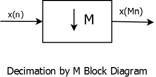
Decimation Block Diagram
Decimation by an integer M corresponds to retaining every \(Mth\) sample and discarding
\(M-1\) samples. In frequency domain, the output \( Y(e^{j\omega})\) is given by \[ Y(e^{j\omega})=\frac{1}{M}X(e^{j\frac{\omega+2k\pi}{M}}) \] for \(k=0,1,....,M-1\)Aliasing is an issue as downsampling ``stretches'' the bandwidth by a factor M. Applying the Shannon sampling theorem, the sampling frequency must be \(f_{s} > 2f_{max}M\) in order to prevent aliasing.An example of aliasing is shown below. A signal consisting of two sinusoids at 50Hz and 130Hz is originally sampled at 1000Hz. It is then downsampled by 2 and 5. In the first case \( f_{s} = 1000 Hz \) is greater than \( 2f_{max}M = 520 Hz \) and, therefore, no aliasing occurs. In the second case, \( f_{s} = 1000 Hz \) is less than \( 2f_{max}M = 1300 Hz \) and we see higher frequency appearing at 350 Hz.
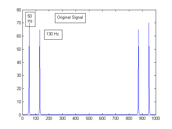
Decimation Example 1
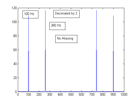
Decimation Example 2
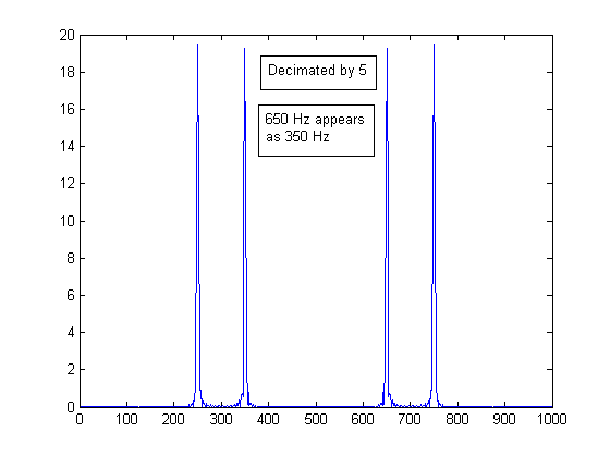
Decimation Example 3
Interpolation
At its simplest, L-interpolation is the process of adding \(L-1\) zeros between sample values of a signal \(x\).
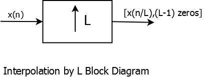
Interpolation Block Diagram
In frequency domain, the output \( Y(e^{j\omega})\) is given by \[ Y(e^{j\omega})=X(e^{jL\omega}) \] ``Imaging'' is a an upsampling phenomena that corresponds to aliasing in the downsampling case. Since an interpolator is compressing a signal, its images appear in the frequency band and depending on the interpolation factor we need a suitable low-pass filter (anti-imaging filter) to filter out these images. Shown below is an example of imaging after upsampling the signal from example above by a factor of 2.
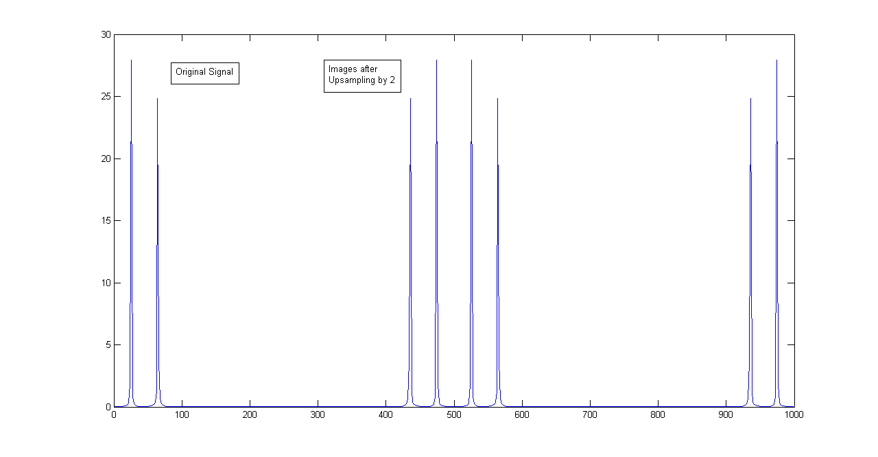
Interpolation Example
Polyphase Representation
Consider a time series \(X(z)=\sum_{n= -\infty}^{\infty} x(n) z^{-n}\). We can use the decimation by \(2\) idea and separate it into its even and odd coefficients.
\[ X(z)=\sum_{n= -\infty}^{\infty} x(2n) z^{-2n}+z^{-1}\sum_{n= -\infty}^{\infty} x(2n+1) z^{-(2n)} \]Let \(P_{0}(z)=\sum_{n= -\infty}^{\infty} x(2n) z^{-n}\) and \(P_{1}(z)=\sum_{n= -\infty}^{\infty} x(2n+1) z^{-n}\) then \(X(z)\) can be written as
\[ X(z)=P_{0}(z^{2})+z^{-1}P_{1}(z^{2}) \]This idea can be extended to any value \(M\) instead of just \(2\).
\[ X(z)=\sum_{n= -\infty}^{\infty} x(Mn) z^{-Mn}+z^{-1}\sum_{n= -\infty}^{\infty} x(Mn+1) z^{-(Mn)}+....+ z^{-(M-1)}\sum_{n= -\infty}^{\infty} x(Mn+M-1) z^{-(Mn)} \]This representation is known as polyphase representation and is used to implement efficient filter banks :
\[ X(z)=\sum_{i=0}^{M-1} P_{i}(z^{M}) z^{-i} \]Filter Banks
Low pass and High pass filters process the signal by allowing only specific frequencies to go through- low pass and high pass frequencies, respectively. This obviously serves a very useful purpose but if these filters are used together then with proper design they can also reconstruct the original signal. A filter bank is a system in which two or more filters are used together to analyze and process a given signal.
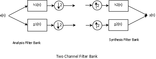
Two Channel Filter Bank
Figure above shows an example of a two channel filter bank. Analysis part of the filter bank decomposes a signal while the synthesis part reconstructs it. \(h_{1}(n)\) and \(h_{2}(n)\) are the low pass filters while \(g_{1}(n)\) and \(g_{2}(n)\) are complementary high pass filters.
Perfect Reconstruction property
Using interpolation and decimation frequency equations, the outputs at the two output nodes of analysis filters are \(\frac{1}{2}(X(\frac{\omega}{2})H_{1}(\frac{\omega}{2})+X(\frac{\omega}{2}+\pi)H_{1}(\frac{\omega}{2}+ \pi))\) and \(\frac{1}{2}(X(\frac{\omega}{2})G_{1}(\frac{\omega}{2})+X(\frac{\omega}{2}+\pi)G_{1}(\frac{\omega}{2}+ \pi))\)
After feeding these two outputs to the two input nodes of synthesis filter, we get( in z-domain)
\[ Y(z)=\frac{1}{2}(H_{1}(z)H_{2}(z)+G_{1}(z)G_{2}(z))X(z) + \frac{1}{2}(H_{1}(-z)H_{2}(z)+G_{1}(-z)G_{2}(z))X(-z) \]For perfect reconstruction, we need \(Y(\omega)=X(\omega)\), this gives us two equations
\[ \frac{1}{2}(H_{1}(z)H_{2}(z)+G_{1}(z)G_{2}(z))= z^{-L} \] and \[ \frac{1}{2}(H_{1}(-z)H_{2}(z)+G_{1}(-z)G_{2}(z)) = 0 \]First equation is called the no distortion equation and the right hand term is a delay element. Second equation is the anti-aliasing equation and needs to be zero for Perfect Reconstruction Filter Bank to serve its purpose.
Orthogonal Filter Banks
Before discussing Orthogonal Filter Banks it is important to discuss orthogonality with respect to a filter \(h(n)\). In wavelet theory, double shift orthogonal filters play a very important role. A filter \(h(n)\) is double shift orthogonal if
\[ \lt h(n),h(n-2k)\gt =\delta(k) \]In the case of two channel filter banks, we can obtain the other three filters just by designing one filter and then using the orthogonality and Perfect Reconstruction properties. Because of double shift orthogonality, we can only design even orthogonal filters. It has been shown that for a given low pass filter \(h_{1}(n)\), the high pass filter can be obtained by alternating flip method, ie., coefficients of low pass filters are flipped and then the sign of every alternate coefficient is flipped. The filters of synthesis filter banks can be obtained by using the no-distortion and no-aliasing equations of the Perfect Reconstruction property. It turns out that for a given \(N+1\)-tap low pass analysis filter \(H_{1}(z)\), the other three filters are
High Pass Analysis Filter \(H_{2}(z) = -z^{-N}H_{1}(z)\) Low Pass Synthesis Filter \(G_{1}(z) = H_{2}(-z)\) High pass Synthesis Filter \(G_{2}(z) = -H_{1}(-z)\)
Biorthogonal Filter Banks
As has been mentioned previously, linear phase filter response is a desirable property in a number of applications and even with all their positives, Orthogonal filter banks are not linear phase filters. Only Haar filter bank is orthogonal and linear phase. Biorthogonal filter banks consists of filters where the filters are not orthogonal to themselves. They are constructed such that the analysis filters are orthogonal to the synthesis filters in addition to being linear phase. Using orthogonality and perfect reconstruction properties of biorthogonal filters, it can be shown that if given two FIR filters \(H_{1}(z)\) and \(G_{1}(z)\), the other two filters in the biorthogonal filter bank can be constructed as \(H_{2}(z)= G_{1}(-z)\) and \(G_{2}(z)= -H_{1}(-z)\)
